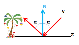
 The model used for analyzing use a simple scene composed of a viewpoint (V..) in which is located the observer or camera, an object to reflect (tree) and a reflecting plane which acts as a mirror.
A ray from the camera “bounce” on the ground at a point which also shows the surface normal (N).
 The angle of incidence of the beam on the mirror surface visual (espejo) this way the same angle as the reflected beam.
Often, and to apply the so-called “ley the fast“, is usually referred to complementary angle, or angle to the normal to the plane or reflective surface at each point (perpendicular).
 To calculate the reflected direction must obtain the symmetric (In ') viewpoint (V..) with respect to the ideal plane that serves as a mirror.
The new address, as can be verified by elementary trigonometry, pass through the imaginary point and the point of incidence of the original beam.
If instead of considering a full beam ray, the model is generalized in the same way.
 Moving the reflection plane, shifting the set of rays reflected and therefore the resulting image will be displaced.
 To change the position of theoretical reflection, Sqirlz Water has a feature that lets you turn it into their software called “Base Line”.
 When activated, change the icons that let you change the position of this line string, indicating that can be used (going to be in gray to have a certain color “active” )
The available functions are:
 Define a polygonal (base line). With the left mouse button will introduce our polygon vertices, while the right mouse button will indicate that we have finished defining the “base line”
Add new segment to the polygon. Lets go by defining a more elaborate and complex contour.
 Mover or trasladar the polygonal. Is equivalent to modifying the position of the reflection plane.

Soften the traverse. Instead of the straight and corner polygonal interpolate a curve which avoids the effects of “straight lines at the edges”.
Consider an example the results of position and re polygonal (base line) in different cases.
First we define the area to reflect the scene, as explained to perform the first example of reflection in water.
In the first example does not activate the “base line”, so that it is placed at the top of the area (red) in which reflection occurs. Is the normal case of use of this technique.
The result is shown in the following image:
- Image Synthesis
- Morphing
- Sqirlz Water Reflections (Introduction to technical)


Must be connected to post a comment.